line and duct burners
FlueFire
Air Heating Burner with Proven supplemental duct firing.
Please sign in to access more documents
Once signed in, you may be able to access additional documents for your account.
Overview
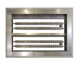
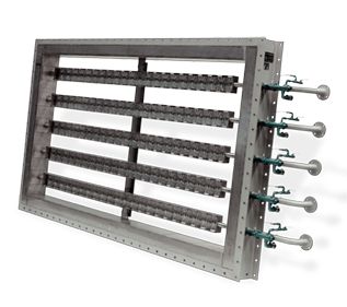
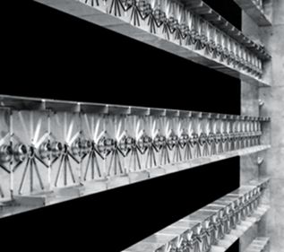
The Eclipse FlueFire burner has become an industry standard for supplemental firing in cogeneration and combined-cycle installations. FlueFire is an in-duct burner which can be located directly in the exhaust gases between the turbine and waste heat boiler. The burner is also suitable for fresh air operation or incineration applications. The FlueFire optimizes the system efficiency as it takes its oxygen requirement from the turbine exhaust gases. The burner can function with inlet temperatures up to 700°C (1300°F) and outlet temperatures up to 1200°C (2200°F). FlueFire is a proven performer in dozens of successful installations around the world.
Features & Benefits:
Features & Benefits:
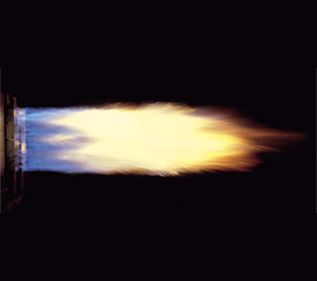
- Excellent flame stability
- Clean combustion with low NOx emissions
- Flame swirl stabilizes the combustion just in front of the burner
- Creates an intimate mixing of the turbine exhaust gases with the fuel
- Exceptional flame stability
Specifications
Air & Combustion Air Specifications
- Process Air Distribution
- ±15% velocity uniformity across the burner required
Pressure Specifications
- Nozzle Gas Pressure
- NG: 169 in wc (421 mbar); Propane: 74 in wc (184 mbar); Butane: 56 in wc (140 mbar)
- Pressure Drop
- 0.3 to 0.5 in wc (75 to 125 Pa)
Processing & Performance Metrics
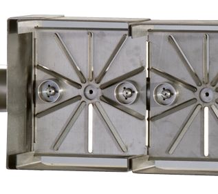
- Module Construction
- Each 150 mm module has a perforated stabilization plate producing local swirl; two gas nozzles + one raw gas port
- Frame Construction
- Heavy steel mounting frame with internal insulation (≈8 in ceramic fiber) and heat‑resistant cladding; sliding end for thermal expansion
- Process Velocity
- FA: 2100 to 2800 ft/min (10 to 14 m/s)
- TEG: 3800 to 5000 ft/min (19 to 25 m/s)
- Minimum Capacity
- 55-95 x 1000 Btu/h (15-25 kW) per 150 mm module (depends on O₂%)
- CO/NOx Emissions
- Emissions depend on process temperature and O₂ level (consult Eclipse)
- Capacity Range
- Up to 1300 x 1000 Btu/h (344 kW) per 150 mm module at 21% O₂
Temperature Control/Measurement
- Temperature Rating
- Downstream: up to 1800 deg F (982 deg C) with 21% O₂ (typical)
- Upstream: up to 1300 deg F (700 deg C)
Combustion, Mixing & Fuel Dynamics
- Oxygen Requirement
- Operational envelope ~11–21% O₂ in process stream; below this, provide external combustion air
Ignition, Flame & Supervision Specifications
- Flame Monitoring
- UV Scanner only
- Ignition Type
- Pilot with ignition plug and flame extension tube; UV proves pilot and main flame; pilot interrupted after light‑off
Control, Safety & Timing Characteristics
- Row/Propagation
- Modules mounted on common manifold to form rows; optional flame propagation plates for cross‑ignition between rows
Product Design & Configuration
- Burner Design
- Modular supplementary firing burner
Applications & Compatibility
- Applications
- Fresh air heating
- High‑temperature process heating
- Turbine exhaust/waste heat boiler firing
Control, Logic & Functional Behavior
- Functions
- Supplementary firing of turbine exhaust gases (TEG) using residual O₂; also applicable to fresh air (FA) heating with high outlet temperatures
Fuel, Gas & Media Specifications
- Fuel Type
- Natural Gas, Propane, Butane; low‑calorific gases per specification
Air & Combustion Air Specifications
- Process Air Distribution
- ±15% velocity uniformity across the burner required
Pressure Specifications
- Nozzle Gas Pressure
- NG: 169 in wc (421 mbar); Propane: 74 in wc (184 mbar); Butane: 56 in wc (140 mbar)
- Pressure Drop
- 0.3 to 0.5 in wc (75 to 125 Pa)
Processing & Performance Metrics
- Module Construction
- Each 150 mm module has a perforated stabilization plate producing local swirl; two gas nozzles + one raw gas port
- Frame Construction
- Heavy steel mounting frame with internal insulation (≈8 in ceramic fiber) and heat‑resistant cladding; sliding end for thermal expansion
- Process Velocity
- FA: 2100 to 2800 ft/min (10 to 14 m/s)
- TEG: 3800 to 5000 ft/min (19 to 25 m/s)
- Minimum Capacity
- 55-95 x 1000 Btu/h (15-25 kW) per 150 mm module (depends on O₂%)
- CO/NOx Emissions
- Emissions depend on process temperature and O₂ level (consult Eclipse)
- Capacity Range
- Up to 1300 x 1000 Btu/h (344 kW) per 150 mm module at 21% O₂
Temperature Control/Measurement
- Temperature Rating
- Downstream: up to 1800 deg F (982 deg C) with 21% O₂ (typical)
- Upstream: up to 1300 deg F (700 deg C)
Combustion, Mixing & Fuel Dynamics
- Oxygen Requirement
- Operational envelope ~11–21% O₂ in process stream; below this, provide external combustion air
Ignition, Flame & Supervision Specifications
- Flame Monitoring
- UV Scanner only
- Ignition Type
- Pilot with ignition plug and flame extension tube; UV proves pilot and main flame; pilot interrupted after light‑off
Control, Safety & Timing Characteristics
- Row/Propagation
- Modules mounted on common manifold to form rows; optional flame propagation plates for cross‑ignition between rows
Product Design & Configuration
- Burner Design
- Modular supplementary firing burner
Applications & Compatibility
- Applications
- Fresh air heating
- High‑temperature process heating
- Turbine exhaust/waste heat boiler firing
Control, Logic & Functional Behavior
- Functions
- Supplementary firing of turbine exhaust gases (TEG) using residual O₂; also applicable to fresh air (FA) heating with high outlet temperatures
Fuel, Gas & Media Specifications
- Fuel Type
- Natural Gas, Propane, Butane; low‑calorific gases per specification
- Process Air Distribution : ±15% velocity uniformity across the burner required
- Nozzle Gas Pressure : NG: 169 in wc (421 mbar); Propane: 74 in wc (184 mbar); Butane: 56 in wc (140 mbar)
- Module Construction : Each 150 mm module has a perforated stabilization plate producing local swirl; two gas nozzles + one raw gas port
- Temperature Rating : Downstream: up to 1800 deg F (982 deg C) with 21% O₂ (typical)|Upstream: up to 1300 deg F (700 deg C)
- Oxygen Requirement : Operational envelope ~11–21% O₂ in process stream; below this, provide external combustion air
- Frame Construction : Heavy steel mounting frame with internal insulation (≈8 in ceramic fiber) and heat‑resistant cladding; sliding end for thermal expansion
- Process Velocity : FA: 2100 to 2800 ft/min (10 to 14 m/s)|TEG: 3800 to 5000 ft/min (19 to 25 m/s)
- Minimum Capacity : 55-95 x 1000 Btu/h (15-25 kW) per 150 mm module (depends on O₂%)
- Flame Monitoring : UV Scanner only
- CO/NOx Emissions : Emissions depend on process temperature and O₂ level (consult Eclipse)
- Row/Propagation : Modules mounted on common manifold to form rows; optional flame propagation plates for cross‑ignition between rows
- Capacity Range : Up to 1300 x 1000 Btu/h (344 kW) per 150 mm module at 21% O₂
- Pressure Drop : 0.3 to 0.5 in wc (75 to 125 Pa)
- Ignition Type : Pilot with ignition plug and flame extension tube; UV proves pilot and main flame; pilot interrupted after light‑off
- Burner Design : Modular supplementary firing burner
- Applications : Fresh air heating|High‑temperature process heating|Turbine exhaust/waste heat boiler firing
- Functions : Supplementary firing of turbine exhaust gases (TEG) using residual O₂; also applicable to fresh air (FA) heating with high outlet temperatures
- Fuel Type : Natural Gas, Propane, Butane; low‑calorific gases per specification
Name
Description
File Size
Date
Size
Category@category|Type@type
Filters
Product Number
Please sign in to view part numbers available for purchase based on your account Sign In
Part Number
Description
Leaf Category
Thumbnail
Add to list
00.4121028.01
NZL,GAS,FFB,LOS,FLUE FIRE BRNR
00.4121028.01
NZL,GAS,FFB,LOS,FLUE FIRE BRNR
00.4121028.25
NZL,GAS,INCINISTAR,STD,D3,7 11X
00.4121028.25
NZL,GAS,INCINISTAR,STD,D3,7 11X
00.4121029.01
PLT,GUIDING END,FLUE FIRE BRNR
00.4121029.01
PLT,GUIDING END,FLUE FIRE BRNR
00.4121051.02
BRNR,SECT,INCINISTAR IS 5,MIDDLE
00.4121051.02
BRNR,SECT,INCINISTAR IS 5,MIDDLE
00.4121051.03
BRNR,SECT,INCINISTAR IS 5,END
00.4121051.03
BRNR,SECT,INCINISTAR IS 5,END
00.4121051.05
BRNR,SECT,INCINISTAR IS 5,INLT NEAR IGN
00.4121051.05
BRNR,SECT,INCINISTAR IS 5,INLT NEAR IGN
00.4121147.00
ROD,IGN,ASY, IS 5 BRNR 00.4121053.07,L1
00.4121147.00
ROD,IGN,ASY, IS 5 BRNR 00.4121053.07,L1
00.4121147.02
ROD,IGN,ASY ECLIPSE BV 00.4121147.02,L1
00.4121147.02
ROD,IGN,ASY ECLIPSE BV 00.4121147.02,L1
00.4121147.03
ROD,IGN,ASY,ECLIPSE BV 00.4121147.03, BR
00.4121147.03
ROD,IGN,ASY,ECLIPSE BV 00.4121147.03, BR
00.4121147.04
ROD,IGN,ASY 05 IS ECLIPSE BV NO. 00.4121
00.4121147.04
ROD,IGN,ASY 05 IS ECLIPSE BV NO. 00.4121
