line and duct burners
LINOFLAME®
The A & B LINOFLAME® burners create short, ribbon-type flames from modular-designed sections with customized drillings. The VF LINOFLAME® produces a similar ribbon of fire but in a wider, V-shaped pattern.
Please sign in to access more documents
Once signed in, you may be able to access additional documents for your account.
Overview
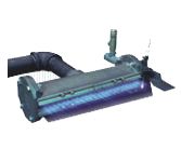
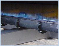
MAXON's style A & B LINOFLAME® Industrial Burners produce short, ribbon-type flames by modular-designed section with customized drillings. Our type VF LINOFLAME® Gas Burners are cast iron, V-faced, modular sections incorporating standardized drillings for interchangeability. Maxon LINOFLAME® Burners are useful for foam laminating, dip tanks, hot oil cooking, glass surface treatments, and general air heating.
Specifications
Environmental Conditions
- Ambient Temperature Range
- Downstream temp limits: ~1000 deg F (recirculated air) or ~1200 deg F (fresh air)
- Styles A/B/C - Ambient/return air over burner should not exceed ~600 deg F (316 deg C), VF - Ambient/return air up to ~800 deg F (427 deg C)
Performance, Flow & Capacity
- Turndown Ratio
- Up to 10:1 (style and premix equipment dependent)
- Heat Release
- Style A - Up to 525,000 Btu/hr per lineal ft @ 7.5 in. wc mixture pressure, Style B - Up to 250,000 Btu/hr per lineal ft @ 13 in. wc mixture pressure, Style C - Up to 25,000 Btu/hr per lineal ft @ 2.5 in. wc mixture pressure
- VFH: up to 600,000 Btu/hr/ft; VFL: up to 300,000 Btu/hr/ft @ 10 in. wc mixture pressure
Combustion, Fuel & Mixing Sub‑Systems
- Section Configuration
- Over 200 modular section types in multiple shapes and sizes
- Pilot Type
- LINOPAK® pilots: atmospheric, pressure, and venturi types; available for low/medium/high gas pressures; UV or flame‑rod flame safeguard
Air & Combustion Air Specifications
- Process Air Velocity
- VF limits up to 3000-4000 SFPM
- ≤ 1000 SFPM for side‑inlet tees (Styles A/B/C)
Material Specifications
- Material
- Cast iron burner bodies; ignition rails in cast iron or alloy (alloy recommended for propane or >400 deg F applications)
Mechanical Design & Adjustment Characteristics
- Manifold Design
- Cast iron air‑gas manifold with drilled face
Processing & Performance Metrics
- Inlet Feed Capacity
- Inlet flange size limits burner footage and total Btu/hr per feed
Ignition, Flame & Supervision Specifications
- Ignition Type
- Direct spark ignition or LINOPAK® pilot systems
- Flame Retention
- Replaceable ignition rail (“zipper channel”) for flame retention and cross‑ignition
- Flame Detection
- Flame rod or UV scanner (configuration dependent)
Fuel, Gas & Media Specifications
- Fuel Type
- Natural Gas, Propane (alloy ignition rails recommended for Propane)
Applications & Compatibility
- Compatible Mixers
- PREMIX® blowers, LG/HG mixing tubes, MULTI‑RATIO™ mixers, VENTITE™ inspirators
Combustion Design & Characteristics
- Combustion Method
- Full air/gas premix producing a ribbon‑type flame
Overview
- Burner Type
- Premix line burners: LINOFLAME® Styles A/B/C (ribbon flame), Type VF (VFL low-capacity, VFH high-capacity)
- VFH (high capacity) and VFL (low capacity) V‑faced burners
Product Design & Configuration
- Burner Style
- Style A, Style B, Style C, and Type “VF” (V‑faced)
- Burner Design
- Premix‑type line burner
- Ambient Temperature Range : Downstream temp limits: ~1000 deg F (recirculated air) or ~1200 deg F (fresh air)|Styles A/B/C - Ambient/return air over burner should not exceed ~600 deg F (316 deg C), VF - Ambient/return air up to ~800 deg F (427 deg C)
- Turndown Ratio : Up to 10:1 (style and premix equipment dependent)
- Section Configuration : Over 200 modular section types in multiple shapes and sizes
- Process Air Velocity : VF limits up to 3000-4000 SFPM|≤ 1000 SFPM for side‑inlet tees (Styles A/B/C)
- Pilot Type : LINOPAK® pilots: atmospheric, pressure, and venturi types; available for low/medium/high gas pressures; UV or flame‑rod flame safeguard
- Material : Cast iron burner bodies; ignition rails in cast iron or alloy (alloy recommended for propane or >400 deg F applications)
- Manifold Design : Cast iron air‑gas manifold with drilled face
- Inlet Feed Capacity : Inlet flange size limits burner footage and total Btu/hr per feed
- Ignition Type : Direct spark ignition or LINOPAK® pilot systems
- Heat Release : Style A - Up to 525,000 Btu/hr per lineal ft @ 7.5 in. wc mixture pressure, Style B - Up to 250,000 Btu/hr per lineal ft @ 13 in. wc mixture pressure, Style C - Up to 25,000 Btu/hr per lineal ft @ 2.5 in. wc mixture pressure|VFH: up to 600,000 Btu/hr/ft; VFL: up to 300,000 Btu/hr/ft @ 10 in. wc mixture pressure
- Fuel Type : Natural Gas, Propane (alloy ignition rails recommended for Propane)
- Flame Retention : Replaceable ignition rail (“zipper channel”) for flame retention and cross‑ignition
- Flame Detection : Flame rod or UV scanner (configuration dependent)
- Compatible Mixers : PREMIX® blowers, LG/HG mixing tubes, MULTI‑RATIO™ mixers, VENTITE™ inspirators
- Combustion Method : Full air/gas premix producing a ribbon‑type flame
- Burner Type : Premix line burners: LINOFLAME® Styles A/B/C (ribbon flame), Type VF (VFL low-capacity, VFH high-capacity)|VFH (high capacity) and VFL (low capacity) V‑faced burners
- Burner Style : Style A, Style B, Style C, and Type “VF” (V‑faced)
- Burner Design : Premix‑type line burner
Name
Description
File Size
Date
Size
Category@category|Type@type
Filters
Product Number
Please sign in to view part numbers available for purchase based on your account Sign In
Part Number
Description
Leaf Category
Thumbnail
Add to list
00295
3" BTTM INLT FLG
00295
3" BTTM INLT FLG
016297-007
PKG, 20/10,3/16 IN. SQ,5.75 IN. LENG
016297-007
PKG, 20/10,3/16 IN. SQ,5.75 IN. LENG
01843
12" A STR BDY
01843
12" A STR BDY
01846
6" A ELB BDY
01846
6" A ELB BDY
01860
LEP END PLT
01860
LEP END PLT
01975
12" A BACK INLT TEE BDY
01975
12" A BACK INLT TEE BDY
02330
12" B ANSI BACK INLT STR BDY
02330
12" B ANSI BACK INLT STR BDY
024214E
LBA-12B-24 BOSSED BI SECT.ISO
024214E
LBA-12B-24 BOSSED BI SECT.ISO
024215E
LBA-12S-24 BOSSED SI SECT.ISO
024215E
LBA-12S-24 BOSSED SI SECT.ISO
024233E
LBA-12B-36 BOSSED BI SECT.ISO
024233E
LBA-12B-36 BOSSED BI SECT.ISO
