driver control
Gas Turbine Control
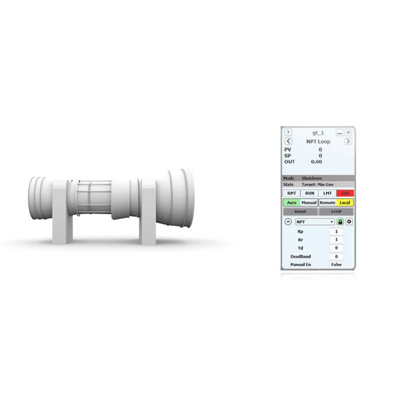
CCC’s gas turbine control apps regulate key variables like power turbine speed for driving compressors and generators. They integrate with other CCC turbomachinery control apps for stable, automated operation.
Please sign in to access more documents
Once signed in, you may be able to access additional documents for your account.
Overview
Modernize and standardize fuel and nozzle controls across a wide range of gas turbine makes and models.
Overview
Gas turbine control applications are designed to manage and optimize the operation of gas turbines, ensuring they run efficiently and reliably. A fuel controller typically regulates power turbine speed by varying the fuel flow through fuel control valves. It can also be used to regulate the electrical power output when used in synchronous generator application. A nozzle control application may be used on some two-shaft gas turbines with a variable-position vanes to regulate exhaust gas temperature (EGT) and gas generator speed (NHP) in conjunction with a fuel control.
What Is It
CCC’s gas turbine control applications, including fuel and nozzle controls, regulate key gas turbine process variables such as power turbine speed for use in driving compressors and generators. They integrate seamlessly with other CCC turbomachinery control applications to provide more stable and automated turbomachinery operation.
How Does It Work?
The usual objective of a gas turbine fuel controller is to vary the fuel flow as needed to maintain the desired power turbine speed regardless of load or fuel quality variations. In some applications, that speed set point is held constant, but it is more commonly varied to achieve a cascade control objective. CCC gas turbine control application integrates seamlessly with performance and antisurge control applications to provide integrated control and protection of the entire turbomachinery train. The set point for the fuel control application would then be controlled by the performance control application.
Some of the key features of the CCC fuel control application include:
Control Systems for such turbines use a nozzle control application in combination with the appropriate fuel control block to manipulate the unit’s interacting control elements. When the turbine is operating within its optimal range:
Overview
Gas turbine control applications are designed to manage and optimize the operation of gas turbines, ensuring they run efficiently and reliably. A fuel controller typically regulates power turbine speed by varying the fuel flow through fuel control valves. It can also be used to regulate the electrical power output when used in synchronous generator application. A nozzle control application may be used on some two-shaft gas turbines with a variable-position vanes to regulate exhaust gas temperature (EGT) and gas generator speed (NHP) in conjunction with a fuel control.
What Is It
CCC’s gas turbine control applications, including fuel and nozzle controls, regulate key gas turbine process variables such as power turbine speed for use in driving compressors and generators. They integrate seamlessly with other CCC turbomachinery control applications to provide more stable and automated turbomachinery operation.
How Does It Work?
The usual objective of a gas turbine fuel controller is to vary the fuel flow as needed to maintain the desired power turbine speed regardless of load or fuel quality variations. In some applications, that speed set point is held constant, but it is more commonly varied to achieve a cascade control objective. CCC gas turbine control application integrates seamlessly with performance and antisurge control applications to provide integrated control and protection of the entire turbomachinery train. The set point for the fuel control application would then be controlled by the performance control application.
Some of the key features of the CCC fuel control application include:
- Fully automated sequences for starting up, shutting down, loading, and idling a turbine
- Fuel Regulation for controlling a selected shaft speed or the power output while protecting against speed, temperature, and pressure extremes
- Overspeed Protection for the power turbine and gas generator using a combination of closed- and open-loop responses (both high-and low-pressure rotors, if applicable)
- Overtemperature Protection and Pressure Limiting
- NHP Acceleration and Deceleration Limiting Control
- Flameout and Overfueling Protection, including scheduled acceleration and deceleration limits
- Surge Protection for the gas generator compressor
- A Dual Fuel feature which divides the total fuel demand between the gas and liquid fuel valves
- Fuel Density Compensation adapts the Fuel Control Valve output signals to variations in fuel density
- Fuel Control Valve Compensation functions adapt the output signals for non-linear control valves
Control Systems for such turbines use a nozzle control application in combination with the appropriate fuel control block to manipulate the unit’s interacting control elements. When the turbine is operating within its optimal range:
- the fuel control application manipulates the fuel flow to regulate the driven-equipment speed (NPT) or generator power output.
- the nozzle control application manipulates the second-stage nozzle to regulate EGT and NHP.
- Increases Uptime: Fast and accurate PID controls combined with loop decoupling and overspeed protection help avoid costly downtime even for a sudden load loss.
- Prevents Damage: By automating the sequences, including critical speed avoidance, it can achieve more safe, reliable, and repeatable start-ups and shutdowns.
Name
Description
File Size
Date
Size
Please sign in to view part numbers available for purchase based on your account Sign In
Part Number
Description
Leaf Category
Thumbnail
Add to list
